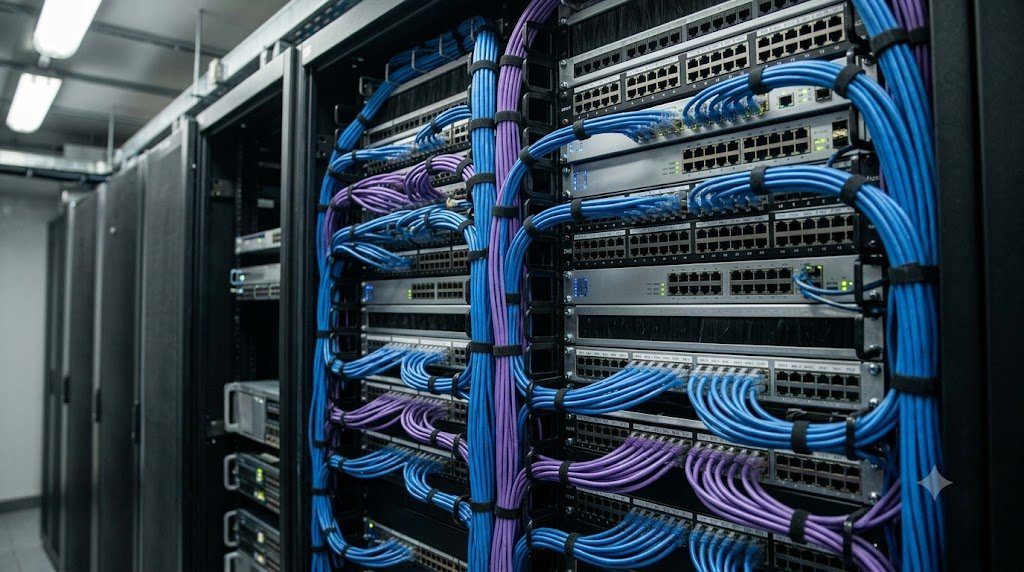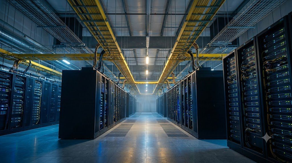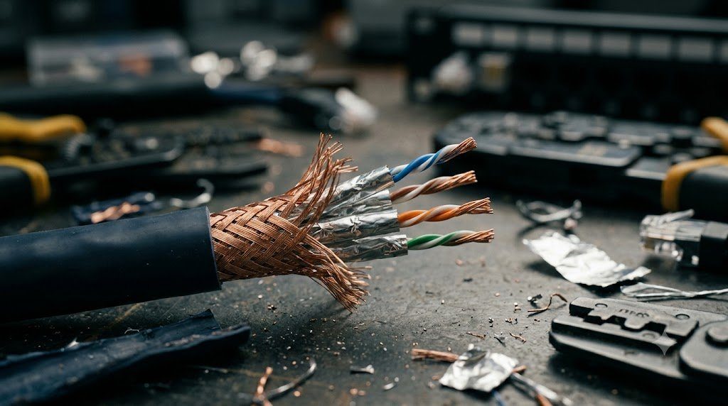
In the foundational architecture of Local Area Networks (LAN), twisted-pair copper cabling remains the most ubiquitous physical transmission medium deployed worldwide. First standardized under IEEE 802.3i (10BASE-T) in 1990, balanced twisted-pair copper media has evolved through successive ANSI/TIA-568 and ISO/IEC 11801 category specifications, scaling transmission bandwidth from 10 Mbps over Category 3 telephone wire up to 40 Gbps over Category 8 shielded cable plants.
Twisted-Pair Category Performance and Bandwidth Spectrum
Each standardized cabling category defines strict physical geometry, wire gauge (AWG), twist density, and maximum operational frequency:
| Cabling Category | Max Frequency Bandwidth | Max Data Rate Supported | Max Certified Channel Length | Physical Cable Construction |
|---|---|---|---|---|
| Category 5e | 100 MHz | 1 Gbps (1000BASE-T) | 100 Meters (328 ft) | 24 AWG, Unshielded (U/UTP), Loose Twists |
| Category 6 | 250 MHz | 1 Gbps (10G up to 37-55m) | 100 Meters (1G) / 55m (10G) | 23 AWG, Internal Cross-Spline Separator |
| Category 6A (Augmented) | 500 MHz | 10 Gbps (10GBASE-T) | 100 Meters (328 ft) | 23 AWG, Shielded (F/UTP or U/FTP) or Optimized UTP |
| Category 7 / 7A | 600 MHz / 1000 MHz | 10 Gbps (Non-standard for 40G) | 100 Meters (328 ft) | Individually Shielded Pairs + Outer Braid (S/FTP) |
| Category 8 (Cat 8.1/8.2) | 2000 MHz (2 GHz) | 25 Gbps / 40 Gbps (40GBASE-T) | 30 Meters (98 ft) Data Center | 22-24 AWG, Fully Shielded (S/FTP), High-Density Foam |
Twist Geometry, Common-Mode Rejection and Internal Crosstalk
The physical twist in a copper pair is not merely decorative; it is a critical electromagnetic filter. By twisting the two insulated copper conductors around each other, external magnetic fields cut across alternating polarities of the loop, self-canceling induced currents. In multi-pair cables (4 pairs / 8 conductors), adjacent pairs run parallel within the outer jacket, threatening Near-End Crosstalk (NEXT) and Far-End Crosstalk (FEXT):
- Varied Twist Rates: To eliminate magnetic coupling between internal pairs, cable manufacturers engineer each of the four pairs with a distinct, mathematically non-harmonious twist pitch (e.g., Pair 1 has 3.1 twists/cm, Pair 2 has 2.4 twists/cm, Pair 3 has 1.8 twists/cm).
- Internal Spline Separator: Category 6 cables introduce an internal polyethylene cross-web (spline) that physically locks the four pairs into separate quadrants, maintaining continuous physical separation ($> 1.0 \text{ mm}$) to suppress NEXT at 250 MHz.
Alien Crosstalk (ANEXT) in 10GBASE-T Networks
When IEEE developed 10GBASE-T (10 Gbps over copper), internal DSP chips could cancel internal NEXT and return loss reflections using sophisticated echo cancellers. However, DSPs cannot cancel Alien Crosstalk (ANEXT)—the electromagnetic noise leaking between completely separate, adjacent cables bundled tightly together in dense wire trays.
Category 6A solved Alien Crosstalk through physical diameter expansion (typically $7.5 \text{ mm}$ to $9.0 \text{ mm}$) and advanced shielding. By keeping adjacent cable cores physically further apart, Power Sum Alien Near-End Crosstalk (PSANEXT) is suppressed beneath the stringent $-67 \text{ dB}$ threshold required to sustain 10 Gbps across full 100-meter channel distances.
Shielding Designations (ISO/IEC 11801): U/UTP, F/UTP, and S/FTP
To eliminate ambiguity regarding cable shielding, ISO/IEC 11801 standardized the syntax XX/YTP, where XX designates overall outer shielding, Y designates individual pair shielding, and TP denotes Twisted Pair: U/UTP (completely unshielded), F/UTP (overall foil shield encasing unshielded pairs), and S/FTP (overall braided wire screen encasing individually foil-shielded pairs). In industrial environments and Category 8 data center links, S/FTP provides absolute immunity to external EMI while demanding proper 360-degree bonding to telecommunications grounding busbars (TGB) to prevent ground loops.
High-Frequency Signal Transmission Line Theory, Characteristic Impedance and Return Loss
When electrical signals traverse balanced twisted-pair copper cables at frequencies exceeding 100 MHz (reaching 2,000 MHz / 2 GHz in Category 8), the conductors cannot be analyzed using simple lumped-element circuit laws (Ohm’s Law and Kirchhoff’s Laws). Instead, the cable must be evaluated as an electromagnetic Distributed Transmission Line governed by the Telegrapher’s Equations. The physical behavior of the cable is defined by four distributed primary line parameters per unit length: Resistance ($R$ in $\Omega/m$), Inductance ($L$ in $H/m$), Conductance ($G$ in $S/m$), and Capacitance ($C$ in $F/m$).
The complex Characteristic Impedance ($Z_0$) of an infinite transmission line is formulated as:
Z0 = √( (R + jωL) / (G + jωC) ) ≈ √( L / C ) ≈ 100 Ω ± 15%
All standardized Ethernet twisted-pair cabling specifies a nominal characteristic impedance of exactly $100 \ \Omega$. If an RJ-45 connector is improperly terminated, wire pairs are untwisted excessively ($> 13 \text{ mm}$ in Cat6A), or the cable is crushed by overtightened zip-ties, the localized geometric spacing between conductors is altered, causing an impedance mismatch. When the high-frequency traveling voltage wave strikes an impedance discontinuity, a portion of the electrical energy reflects backward toward the transmitter:
Reflection Coefficient (Γ) = ( Zload – Z0 ) / ( Zload + Z0 ) | Return Loss (dB) = -20 · log10( |Γ| )
ho / (\pi f \mu)}$) shrinks to just 1.5 microns at 2,000 MHz. Consequently, the effective AC resistance of the copper wire increases with the square root of frequency ($R_{ac} \propto \sqrt{f}$), dramatically accelerating signal insertion loss attenuation and requiring Category 8 cables to utilize heavier 22 AWG copper cores restricted to 30-meter channel lengths.
Power over Ethernet (PoE++ / IEEE 802.3bt) Thermal Dissipation in Cable Bundles
Under IEEE 802.3bt (Type 4 PoE++), Ethernet cables carry up to 90 watts of DC electrical power (up to 960 mA per pair across all 4 pairs) concurrently with 10G data traffic to power high-draw PTZ cameras, Wi-Fi 7 Access Points, and IoT digital signage. The DC current flows through the copper conductor resistance, generating resistive heat ($P_{loss} = I^2 R$). In large cable trays where hundreds of Category 6A cables are bundled tightly together in dense bundles, thermal heat cannot escape. Temperatures in the bundle core can rise by over $20^\circ ext{C}$, degrading cable insulation life and accelerating high-frequency insertion loss attenuation by up to 0.4% per degree Celsius.
Data Center Failure Analysis: Shielding Ground Loops and High-Temperature PoE Bundling
During a major upgrade at a commercial cloud data center, technicians installed hundreds of Category 6A Shielded (F/UTP) cable runs connecting core distribution switches to server cabinets across different server halls. Shortly after commissioning, switch interfaces began logging massive cyclic bursts of Cyclic Redundancy Check (CRC) errors and physical link flap events, causing packet dropouts across the storage network.
A physical layer audit using Fluke network analyzers and digital oscilloscopes uncovered two catastrophic installation errors: Shielding Ground Loops and PoE Thermal Derating. Technicians had terminated the metal foil shield of the Cat6A cables to ground at both ends: at the server rack grounding busbar and at the central telecommunications room busbar. Because the two server halls were fed by separate electrical substations with slightly different ground potentials (a potential difference of just $1.8 \text{ V}$), the cable shield became an unintended return conductor, carrying 60 Hz ground current that inductively coupled noise directly into the twisted copper data pairs.
PoE Bundle Melting Teardown and Fire Safety Standards
Furthermore, technicians had bundled 96 Category 6A cables tightly together using plastic zip-ties to feed high-draw 90W PoE++ LED lighting fixtures. Thermal imaging cameras revealed temperatures inside the bundle core exceeding $72^\circ ext{C}$, exceeding the cable’s $60^\circ ext{C}$ PVC jacket rating and melting the outer jackets. Network engineering standards mandate limiting high-power PoE bundles to maximum 24 cables, secured loosely with Velcro hook-and-loop ties in ventilated cable trays to permit convective heat dissipation.
Field Certification Testing: Fluke DSX-8000 Diagnostics and Parameter Analysis
Before an enterprise structured copper cabling installation can be legally certified and warrantied by cable manufacturers (such as CommScope, Panduit, or Belden for 25-year warranties), every single installed link must undergo formal non-destructive testing using certified Level 2G field testers (such as the Fluke DSX-8000 CableAnalyzer). The test instrument injects high-frequency swept sinusoidal signals across all four wire pairs from 1 MHz up to 500 MHz (Cat6A) or 2,000 MHz (Cat8), measuring critical transmission parameters:
- Wire Map: Verifies pin-to-pin continuity according to ANSI/TIA T568A or T568B pinouts; detects open circuits, short circuits, reversed pairs, crossed pairs, and split pairs.
- Insertion Loss (Attenuation): Measures the reduction in signal power over the length of the link (expressed in negative dB). Excessive insertion loss indicates over-length cables or high ambient temperatures.
- Near-End Crosstalk (NEXT) and PS-NEXT: Measures signal leakage between adjacent pairs at the near end; fails if wire pairs are untwisted too far at the punch-down jack.
- Return Loss: Measures impedance uniformity; fails if cables are pinched, kinked, or exceed maximum bend radius.
- Propagation Delay & Delay Skew: Measures transit time differences between pairs; delay skew must not exceed 50 nanoseconds across the 100-meter channel to prevent receiver bit misalignment in multi-gigabit Ethernet.
Single-Pair Ethernet (SPE / IEEE 802.3cg/ch) and Industrial IoT Frontiers
While traditional enterprise Ethernet has relied on four-pair (8-conductor) balanced copper cabling for three decades, the exponential growth of industrial automation, building operational technology (OT), and automotive vehicular networks has driven the standardization of Single-Pair Ethernet (SPE), ratified under IEEE 802.3cg (10BASE-T1L), 802.3bw (100BASE-T1), and 802.3ch (multi-gigabit automotive Ethernet).
Single-Pair Ethernet transmits bi-directional full-duplex data and electrical power (Power over Data Lines / PoDL) across a single twisted copper pair (2 conductors). 10BASE-T1L delivers 10 Mbps data transmission across astonishing physical distances up to 1,000 meters (1 kilometer / 3,280 feet), completely replacing legacy, proprietary RS-485 and Fieldbus industrial serial links with native, end-to-end IP communications directly to factory floor valves, temperature sensors, and robotic actuators.
Integrated Ethernet Systems Engineering: Physical Transmission, Switching Matrices and Fabric Resiliency
Since its invention at Xerox PARC by Robert Metcalfe in 1973, Ethernet (IEEE 802.3) has evolved from a primitive 2.94 Mbps coaxial shared-medium broadcast bus into the universal, undisputed physical and data link layer foundation of global digital computing. Modern enterprise campuses and cloud data centers depend upon the seamless interoperability of Balanced Twisted-Pair Copper, High-Speed Optical Transceivers, Wire-Rate Layer 2 Switching ASICs, and Multi-Chassis Link Aggregation.
The engineering design philosophy governing modern Ethernet infrastructure encompasses four essential tenets:
- Transmission Line Integrity (Layer 1): Enforcing rigorous physical media standards: balanced differential signaling and alien crosstalk suppression in Category 6A/8 copper cabling, and total internal reflection waveguides in singlemode (OS2) and multimode (OM4) optical fibers. Designing link budgets with adequate optical power margins and enforcing IEC 61300-3-35 connector inspection standards guarantees zero physical layer bit errors.
- Deterministic Layer 2 Forwarding (Layer 2): Micro-segmenting local broadcast domains via IEEE 802.1Q VLAN trunking and Content-Addressable Memory (CAM) tables. Forwarding ASICs execute wire-rate MAC learning and filtering in silicon, preventing unknown unicast flooding and isolating departmental network domains.
- Loop Elimination and Active-Active Multi-Pathing: Replacing blocking Spanning Tree topologies with dynamic Link Aggregation Groups (LACP / IEEE 802.3ad), Multi-Chassis MLAG, and data center VXLAN EVPN overlays. This enables 100% active-active link utilization, sub-second deterministic failover, and non-blocking bisectional bandwidth across enterprise fabrics.
- Hardware Security Hardening: Implementing hardware-enforced port security suites: Storm Control, BPDU Guard, Root Guard, DHCP Snooping, Dynamic ARP Inspection (DAI), and MAC limiting to permanently neutralize broadcast storms, rogue switches, and Layer 2 man-in-the-middle attacks.
Energy Efficient Ethernet (EEE / IEEE 802.3az) and Green Enterprise Switching
In massive enterprise campus and data center installations housing tens of thousands of active switch ports, idle electrical consumption represents a major operational cost. Modern switches enforce Energy Efficient Ethernet (EEE / IEEE 802.3az). During periods of low traffic activity, the physical layer transceiver enters Low Power Idle (LPI) mode, powering down internal transmitter circuitry while maintaining link synchronization, reducing physical interface power consumption by up to 70% and contributing to enterprise corporate sustainability mandates.