In modern mission-critical data center facilities, electrical power consumption and thermal heat dissipation represent the single largest operational expenditure (OpEx) and the primary physical constraint bounding compute density. Every watt of electrical power consumed by server CPUs, GPU clusters, high-speed routing ASICs, and storage arrays is converted almost entirely into Thermal Heat via resistive dissipation ($P = I^2 R$). Without rigorous thermodynamic airflow engineering, hot exhaust air recirculates into server air intakes, triggering thermal CPU throttling, hardware component premature failure, and catastrophic facility shutdown.
Hot Aisle / Cold Aisle Layout Geometry
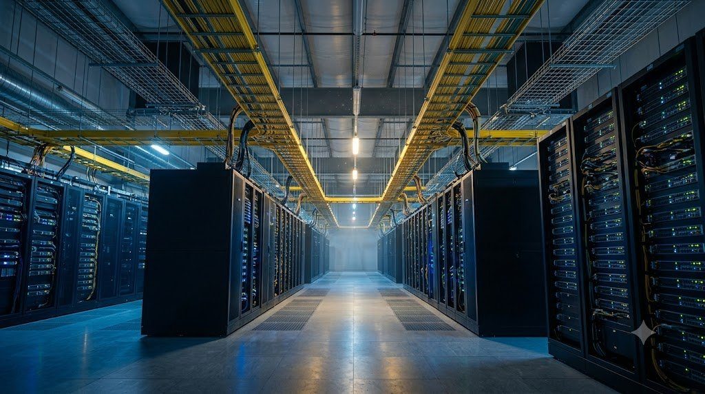
Historically, legacy computer rooms arranged server racks in uniform rows facing the same direction, causing the exhaust heat of Row 1 to blow directly into the air intake of Row 2. Modern data centers arrange equipment racks in alternating, opposing rows under the standardized Hot Aisle / Cold Aisle Topology (codified by ASHRAE TC 9.9 guidelines):
| Aisle Classification | Physical Rack Orientation | Air Temperature Range (ASHRAE A1) | Airflow Fluid Dynamics Function |
|---|---|---|---|
| Cold Aisle | Server Rack Front Faces (Intakes) Opposing Each Other | 18°C to 27°C (64.4°F to 80.6°F) | Supplies clean, chilled air exclusively to equipment intake fans. |
| Hot Aisle | Server Rack Rear Faces (Exhausts) Opposing Each Other | 35°C to 45°C (95°F to 113°F) | Captures concentrated high-temperature exhaust for return to CRAH units. |
Aisle Containment Engineering: Hot Aisle vs. Cold Aisle Containment
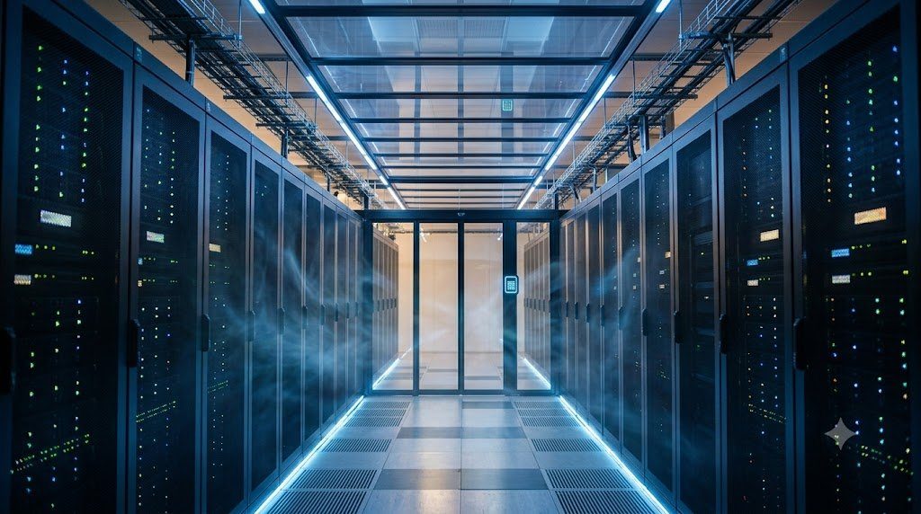
While uncontained hot/cold aisles improve thermal distribution, ambient room air still mixes at the ends of rows and over the tops of racks. To achieve true thermodynamic separation, modern facilities deploy physical Aisle Containment Systems utilizing clear polycarbonate ceiling panels and automated end-of-row sliding doors:
- Cold Aisle Containment (CAC): Encloses the cold aisle with a roof and doors, transforming the cold aisle into a pressurized chilled air plenum. CAC is simple to retrofit in existing facilities with raised floor access; however, the remainder of the server hall becomes a hot ambient environment ($> 38^\circ\text{C}$), which can be uncomfortable for technicians working outside the contained rows.
- Hot Aisle Containment (HAC): Encloses the hot aisle, funneling hot exhaust air directly into an overhead drop-ceiling return plenum that routes air directly back to CRAH cooling coils. HAC is thermodynamically superior: the entire general data center hall remains a comfortable cold environment, and CRAH units operate at peak thermodynamic efficiency because heat transfer across cooling coils increases dramatically as the temperature differential ($\Delta T$) between exhaust air and cooling water widens.
Power Usage Effectiveness (PUE) and Facility Energy Efficiency
The international benchmark metric governing data center energy efficiency, standardized by The Green Grid and ISO/IEC 30134-2, is Power Usage Effectiveness (PUE):
PUE = Total Facility Energy / IT Equipment Energy ≥ 1.0
A legacy, uncontained data center typically exhibits a dismal PUE of $1.8$ to $2.0$—meaning that for every 100 kW of power consumed by computing servers, an additional 80 to 100 kW is wasted running chillers, pumps, fans, and lighting. Through hot aisle containment, variable-speed fan motors, and elevated supply temperatures (operating closer to ASHRAE’s upper $27^\circ\text{C}$ threshold), modern hyperscale facilities achieve world-class PUE ratings between 1.10 and 1.15.
Emerging High-Density Cooling: Direct-to-Chip Liquid and Immersion Cooling
As artificial intelligence (AI) and machine learning workloads deploy high-density GPU servers (such as NVIDIA HGX clusters) consuming upwards of 40 kW to 100 kW per rack, traditional air cooling reaches its physical thermodynamic limit: air cannot physically carry away that volume of heat without requiring hurricane-velocity fan speeds. Next-generation facilities are transitioning to Direct-to-Chip Liquid Cooling (DLC) and Two-Phase Immersion Cooling. Dielectric coolant or chilled water is pumped directly through copper cold plates clamped to GPU dies, leveraging liquid’s $1,000\times$ greater volumetric heat capacity compared to air to support ultra-dense compute nodes.
Computational Fluid Dynamics (CFD) Airflow Modeling and Psychrometric Enthalpy
Modern data center facility design relies on advanced Computational Fluid Dynamics (CFD) numerical simulations to model air velocity vectors, pressure differentials, and thermal gradients across high-density server halls before physical construction begins. CFD software solves the Navier-Stokes equations governing turbulent fluid flow coupled with the energy conservation equation, predicting thermal recirculation hot spots and airflow short-circuiting across thousands of server equipment racks.
Thermal engineers analyze data center cooling performance on a Psychrometric Chart, plotting dry-bulb temperature, relative humidity, and Specific Enthalpy ($h$ in kJ/kg). The rate of thermal heat removal from a server rack by circulating air is formulated as:
Q̇ = ṁ · cp · ΔT = ρ · V̇ · cp · (Texhaust – Tintake) [Watts]
Where $\dot{m}$ is mass airflow rate, $\rho \approx 1.184 \text{ kg/m}^3$ is air density, $\dot{V}$ is volumetric airflow in cubic feet per minute (CFM), and $c_p \approx 1.005 \text{ kJ/(kg}\cdot\text{K)}$ is the specific heat capacity of dry air. In practical engineering terms, removing 1,000 watts (1 kW) of heat from a server rack under a standard $11^\circ\text{C}$ ($20^\circ\text{F}$) temperature rise requires approximately 160 CFM of chilled air ($CFM = 3.16 \times Watts / \Delta T$).
Economizer Free-Cooling Cycles (Air-Side and Water-Side Economization)
To achieve world-class PUE ratings ($PUE < 1.15$), hyperscale data centers deploy Economizer Free-Cooling Systems. In cooler climates (such as Dublin, Sweden, or Oregon), outdoor ambient temperatures drop below server supply requirements for over 6,000 hours per year. Under Air-Side Free Cooling, mechanical refrigeration chillers are powered off completely: outdoor air is filtered, mixed with warm return air to maintain humidity, and ducted directly into the data center hall. Under Water-Side Economization, cooling tower water bypasses chillers to cool the closed chilled-water loop via plate-and-frame heat exchangers, providing free cooling and slashing megawatt-hours of utility electrical consumption.
Enterprise Server Hall Meltdown: Raised-Floor Static Pressure Collapse and Perforated Tile Misplacement
In an enterprise financial data center housing 200 server racks on a legacy 24-inch raised-floor plenum cooling system, facility managers experienced recurring, severe thermal alarms: high-density database servers located in Rows 7 and 8 were repeatedly shutting down due to CPU thermal trip protection ($T_{die} > 95^\circ\text{C}$), even while the facility’s massive Computer Room Air Handler (CRAH) chillers were running at 100% maximum capacity, blowing arctic $12^\circ\text{C}$ air beneath the floor.
A comprehensive Computational Fluid Dynamics (CFD) airflow audit and physical thermal anemometer survey uncovered severe Static Pressure Plenum Collapse and Air Short-Circuiting. Server technicians attempting to ‘cool down’ specific hot spots had randomly added high-flow perforated floor tiles (60% open area) directly in front of the CRAH discharge units and across perimeter open walkways.
Thermal Re-Balancing and Solid Tile Airflow Optimization
Facility engineers executed immediate aerodynamic re-balancing: (1) Replacing all perforated tiles near the CRAH discharge with solid floor tiles, allowing air velocity to settle and convert into a pressurized static air plenum ($P_{static} > 25 \text{ Pa}$), (2) Installing brush grommets across all cable cutout floor penetrations to prevent unmanaged air leakage, and (3) Erecting rigid polycarbonate Cold Aisle Containment (CAC) roofs and sliding end-doors, raising server intake airflow volume by 300% and stabilizing CPU die temperatures at a cool $52^\circ ext{C}$.
Data Center Infrastructure Management (DCIM) and Real-Time IoT Environmental Monitoring
Maintaining thermal containment integrity across multi-megawatt data centers requires continuous, automated monitoring through Data Center Infrastructure Management (DCIM) software suites (such as Schneider Electric EcoStruxure or Vertiv Trellis). Equipment racks are instrumented with wireless IoT environmental sensor clusters deployed according to ASHRAE standards:
- Top, Middle, and Bottom Intake Temperature Sensors: Placed on the front face of each rack at heights of 10U, 22U, and 36U to measure vertical thermal stratification and verify that intake air remains within ASHRAE Recommended limits ($18^\circ ext{C}$ to $27^\circ ext{C}$).
- Differential Static Pressure Sensors ($\Delta P$): Measures the pressure difference between the cold aisle and hot aisle; maintains positive pressure ($+5$ to $+10 \text{ Pa}$) to prevent hot air infiltration.
- Under-Floor Water Leak Detection Rope Sensors: Deployed beneath raised floors and CRAH cooling loops to detect condensation or pipe ruptures within seconds.
Zero-Carbon Data Centers: District Heating Integration and Liquid Immersion Horizons
As global data center electrical consumption approaches 2% to 3% of worldwide electricity generation, regulatory bodies (such as the European Union Energy Efficiency Directive / EED) enforce strict sustainability mandates requiring data centers to report their Power Usage Effectiveness (PUE) and implement Waste Heat Reuse.
Leading modern data center facilities in northern Europe and North America are engineered as municipal thermal utility generators: the hot liquid coolant exiting liquid-cooled server racks ($T_{coolant} \approx 50^\circ\text{C}$ to $65^\circ\text{C}$) is pumped directly into municipal District Heating Networks, providing clean, zero-carbon heating and hot water to thousands of residential homes and public buildings. Paired with full Two-Phase Liquid Immersion Cooling, data centers achieve near-ideal PUE ratings of 1.02 to 1.05, permanently eradicating mechanical refrigeration chillers and ushering in a new era of environmentally sustainable computing.
Integrated Infrastructure Engineering: Physical Plants, Data Center Fabrics and Software-Defined WAN
Beneath the abstract protocols, software routing daemons, and application data streams of modern telecommunications lies the physical reality of Network Infrastructure Engineering. High-performance enterprise networks, hyperscale cloud data centers, and global telecom central offices rely on the uncompromising convergence of Structured Cabling Plants, Non-Blocking Clos Topologies, Rack Thermal Fluid Dynamics, and Software-Defined Overlay Fabrics.
The operational framework of carrier-grade network infrastructure comprises four interdependent disciplines:
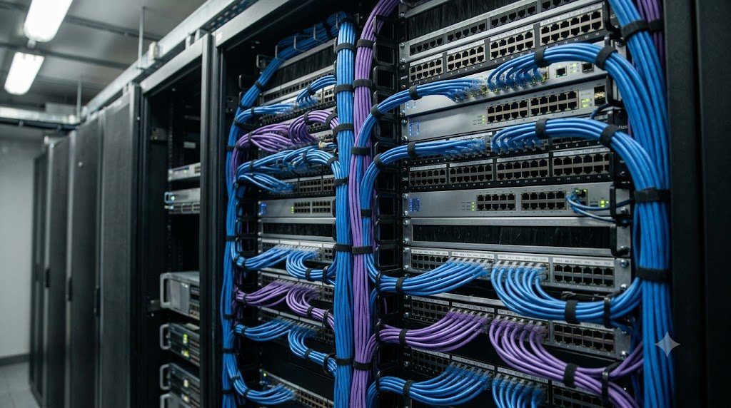
- Physical Plant Structured Cabling (ANSI/TIA-568): Engineering modular, standardized structured cabling subsystems across Entrance Facilities, Equipment Rooms, and Telecommunications Rooms. Managing 100-meter horizontal channel constraints, MPO/MTP multi-fiber trunk polarity (Methods A, B, C), and enforcing Tier 1 (OLTS) and Tier 2 (OTDR) field certification testing guarantees physical layer longevity across multiple active hardware lifecycles.
- Non-Blocking Data Center Clos Fabrics: Replacing legacy three-tier spanning-tree architectures with modern two-tier Spine-and-Leaf Clos networks. Leveraging Layer 3 eBGP routing (RFC 7938) and Equal-Cost Multi-Path (ECMP) delivers deterministic two-hop latency, non-blocking bisectional bandwidth, and 100% active-active link utilization optimized for intensive East-West cloud and AI cluster traffic.
- Thermodynamic Rack Thermal Management: Eliminating bypass air mixing through strict Hot Aisle / Cold Aisle containment (HAC/CAC) adhering to ASHRAE TC 9.9 guidelines. Maximizing CRAH heat exchange efficiency and deploying blanking panels slashes data center energy waste, driving Power Usage Effectiveness (PUE) down to world-class ratings beneath 1.15.
- Software-Defined WAN (SD-WAN) and SASE: Decoupling logical corporate WAN overlays from physical telecommunications underlays. Dynamic application-aware routing over encrypted IPsec tunnels provides automated circuit failover across commodity broadband and 5G, converged with cloud-native Secure Access Service Edge (SASE) security architectures to protect distributed global enterprises.
Data Center Infrastructure Management (DCIM) and Predictive Capacity Planning
Maintaining multi-megawatt mission-critical infrastructure requires 24/7/365 automated visibility through integrated Data Center Infrastructure Management (DCIM) suites. IoT sensor networks continuously sample rack intake temperatures, static pressure differentials, and electrical power branch circuit metrics. Predictive capacity planning algorithms forecast electrical draw and cooling headroom months in advance, ensuring that enterprise facilities expand compute density safely without thermal throttling or electrical circuit breaker tripping.