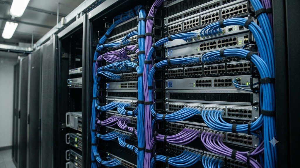
Behind every high-performance enterprise data center, campus network, and telecom central office lies the physical foundation of modern communications: the Structured Cabling System (SCS). Without standardized physical cabling architecture, telecommunications facilities rapidly descend into a tangled, unmanageable ‘spaghetti’ of ad-hoc point-to-point patch cords. This disorder introduces massive cable strain, blocks cooling airflow pathways through equipment racks, causes unpredictable insertion loss, and makes troubleshooting network outages nearly impossible.
The Six Standardized Subsystems of Structured Cabling
ANSI/TIA-568 partitions an enterprise building’s physical cabling plant into six distinct, interconnected functional subsystems:
| Subsystem Number | Structured Cabling Subsystem | Physical Scope & Location | Primary Media & Engineering Standards |
|---|---|---|---|
| Subsystem 1 | Entrance Facility (EF) | Service entrance where carrier telco demarcs enter building. | Underground Singlemode OS2 OSP cables, Lightning arresters. |
| Subsystem 2 | Equipment Room (ER) | Central computerized server room housing core routers and switches. | High-density fiber patch panels, SAN fabrics, core UPS systems. |
| Subsystem 3 | Backbone (Riser) Cabling | Interconnects Entrance Facilities, Equipment Rooms, and TRs across floors. | Multi-strand Singlemode OS2 & Multimode OM4 fiber trunks. |
| Subsystem 4 | Telecommunications Room (TR) | Enclosures housing intermediate distribution switches on each floor. | Horizontal cross-connects, Cat6A patch panels, PoE power. |
| Subsystem 5 | Horizontal Cabling | Wiring extending from the TR patch panel out to individual work areas. | Cat6 / Cat6A 4-pair UTP/STP copper runs (Max 90m solid core). |
| Subsystem 6 | Work Area (WA) | Physical outlet faceplates and patch cords connecting user endpoints. | RJ-45 keystone jacks, Cat6A stranded patch cords (Max 10m total). |
The 100-Meter Channel Limit: Permanent Link vs. Channel Formulation
In balanced twisted-pair copper horizontal cabling (Cat5e through Cat6A), the maximum permissible transmission distance specified by TIA-568 is strictly 100 meters (328 feet). This 100-meter limit is mathematically partitioned into two distinct test configurations:
- The Permanent Link (Max 90 Meters): The static, permanent wiring installed inside building walls, ceilings, and conduit raceways extending from the TR patch panel to the work area wall outlet jack. The permanent link utilizes solid-core copper conductors (typically 23 AWG in Cat6A) designed for low attenuation and punch-down reliability.
- The Channel (Max 100 Meters): The complete end-to-end circuit, including the 90-meter permanent link plus all flexible patch cords: up to 5 meters of patch lead at the TR cross-connect, and up to 5 meters of patch lead at the work area desk ($90\text{m permanent} + 10\text{m patch cords} = 100\text{m total channel}$). Patch cords utilize stranded copper conductors to withstand continuous mechanical bending without metal fatigue.
MPO/MTP High-Density Fiber Optic Trunking Architecture
In modern high-density data centers operating 40G, 100G, and 400G networks, terminating individual duplex LC fiber patch cords for hundreds of switch ports creates severe congestion. Enterprise data centers deploy MPO/MTP (Multi-fiber Push-On) Connector Trunks. A single MPO connector terminates 8, 12, 16, or 24 individual optical glass fibers within a single compact rectangular ferrule measuring just 7 mm wide.
Deploying MPO systems requires rigorous management of Optical Polarity (TIA-568 Method A, Method B, Method C) to guarantee that the transmitter laser on Switch A aligns precisely with the receiver photodiode on Switch B. In high-speed 100GBASE-SR4 networks, MPO-12 connectors utilize four fibers to transmit ($4 \times 25\text{G}$) and four fibers to receive, leaving the center four fibers unused.
Structured Cable Testing and Certification: Tier 1 vs. Tier 2
Before an enterprise structured cabling plant is commissioned, every link must undergo formal non-destructive certification using calibrated field testers (such as the Fluke DSX-8000). For optical fiber, certification is bifurcated into two tiers: Tier 1 Certification utilizes an Optical Loss Test Set (OLTS) to measure absolute insertion loss and link length against specified link budgets; Tier 2 Certification adds an Optical Time-Domain Reflectometer (OTDR) trace to inspect every individual connector reflectance, fusion splice loss, and micro-bend along the fiber strand, guaranteeing zero hidden flaws.
Optical Time-Domain Reflectometry (OTDR) Rayleigh Backscattering Physics
During Tier 2 certification of high-performance enterprise and carrier-grade optical cabling plants, field technicians deploy the most sophisticated diagnostic instrument in optical engineering: the Optical Time-Domain Reflectometer (OTDR). An OTDR functions as a high-precision optical radar for glass fiber: it injects a high-power, nanosecond-duration laser light pulse down the core and measures the minute optical power reflected backward over time ($t$).
An OTDR trace measures two fundamentally distinct optical reflection physics phenomena:
- Rayleigh Backscattering: Natural, continuous microscopic density fluctuations frozen into the silica glass matrix during manufacturing cause light photons to scatter in all directions. A tiny fraction of this scattered light travels backward toward the OTDR detector. The resulting downward-sloping linear trace line indicates the fiber’s intrinsic attenuation coefficient ($\alpha$ in dB/km).
- Fresnel Reflection: Occurs at sharp refractive index boundaries ($n_1 \rightarrow n_2$)—such as mechanical mated connector pairs, mechanical splices, or physical fiber breaks where glass meets air. Fresnel reflection produces sharp upward reflective spikes on the OTDR trace, allowing technicians to calculate exact Optical Return Loss (ORL) and reflectance down to $-70 \text{ dB}$.
Optical Polarity Methods A, B, and C for Multi-Fiber MPO Trunks
In high-density 12-fiber and 24-fiber MPO trunks (TIA-568.3-D), maintaining correct optical polarity is critical: the transmit laser on Position 1 must connect to the receive photodiode on the remote switch, without manual cross-patching. TIA-568 standardizes three distinct polarity systems: Method A (Key-Up to Key-Down straight-through trunk) utilizes straight trunks with Type A cassettes, requiring a special flipped A-to-B patch cord at one end; Method B (Key-Up to Key-Up reversed trunk) inverts the entire fiber order (Position 1 connects to Position 12), enabling standard A-to-B patch cords at both ends; and Method C (Pair-Wise Flipped) flips adjacent fiber pairs (1-2, 3-4), optimized for duplex LC breakouts.
Corporate Data Center Commissioning Failure: The Inverted MPO Polarity Catastrophe
During the multi-million-dollar commissioning of a new primary financial data center facility, enterprise network engineers connected fifty newly installed Top-of-Rack (ToR) switches to the core spine directors via pre-terminated 12-fiber MPO/MTP Singlemode Trunk Cables operating 100GBASE-PSM4 transceivers. Upon powering on the core directors, every single 100G uplink port remained stubbornly in an Operational Down / No Light Detected state.
Initial suspicion fell on expensive optical transceiver modules. However, testing individual transceivers with loopback plugs confirmed that all optical hardware was 100% operational. A physical layer audit using visual fault locators (VFL red laser pens) and optical power meters uncovered an MPO Optical Polarity Inversion Error throughout the entire structured cabling installation.
Fluke MultiFiber Pro Field Testing and Polarity Correction
The engineering team deployed automated Fluke MultiFiber Pro Optical Power Meters capable of scanning all 12 fibers in an MPO connector simultaneously in under 6 seconds. The field tester mapped the individual fiber routing, identifying the exact cassette misalignments. The contractor replaced the patch cords with Type-B rolled jumpers, restoring proper Tx-to-Rx alignment and bringing all fifty 100G spine-and-leaf trunks online with verified insertion loss beneath $1.2 \text{ dB}$ across every channel.
Cable Plant Administration Standards: ANSI/TIA-606-C Labeling and Infrastructure CAD
An enterprise structured cabling plant is only as reliable as its physical documentation and labeling scheme. Standardized under ANSI/TIA-606-C (Administration Standard for Telecommunications Infrastructure), all telecommunications pathways, spaces, equipment racks, patch panels, and individual cable drops must be systematically labeled using machine-printed, durable laminated labels following a standardized alphanumeric format:
Standard Format: [Building]-[Floor][Room].[Rack]-[PatchPanel]-[Port] (e.g., B02-2TR.RK04-P01-24)
Every cable must be labeled at both ends within 30 cm of termination. Furthermore, cabling contractors must deliver comprehensive As-Built CAD Drawings and complete digital certification test records (.flw format exported from Fluke LinkWare), providing facility managers with an exact physical map of every copper drop and fiber splice across the entire building lifecycle.
Sustainability Standards: Low Smoke Zero Halogen (LSZH) and Green Cabling
Modern international building codes and data center infrastructure standards enforce strict environmental and fire safety requirements governing the chemical composition of telecommunications cabling jackets. In legacy installations, cable jackets utilized Polyvinyl Chloride (PVC) treated with halogenated flame retardants. In the event of a commercial building fire, burning PVC releases dense black smoke and highly toxic, corrosive Hydrogen Chloride (HCl) gas, which asphyxiates building occupants and permanently destroys server electronic circuit boards.
Modern enterprise installations universally mandate Low Smoke Zero Halogen (LSZH / IEC 60332) and plenum-rated (CMP / NFPA 262) cabling. LSZH jackets are formulated with thermoplastic compounds that emit negligible smoke and zero toxic halogens when subjected to extreme heat, preserving human life and protecting multi-million-dollar computing hardware during fire incidents. Furthermore, sustainability initiatives mandate cradle-to-cradle recyclable packaging and lead-free copper refining across the entire telecommunications manufacturing lifecycle.
Integrated Infrastructure Engineering: Physical Plants, Data Center Fabrics and Software-Defined WAN
Beneath the abstract protocols, software routing daemons, and application data streams of modern telecommunications lies the physical reality of Network Infrastructure Engineering. High-performance enterprise networks, hyperscale cloud data centers, and global telecom central offices rely on the uncompromising convergence of Structured Cabling Plants, Non-Blocking Clos Topologies, Rack Thermal Fluid Dynamics, and Software-Defined Overlay Fabrics.
The operational framework of carrier-grade network infrastructure comprises four interdependent disciplines:
- Physical Plant Structured Cabling (ANSI/TIA-568): Engineering modular, standardized structured cabling subsystems across Entrance Facilities, Equipment Rooms, and Telecommunications Rooms. Managing 100-meter horizontal channel constraints, MPO/MTP multi-fiber trunk polarity (Methods A, B, C), and enforcing Tier 1 (OLTS) and Tier 2 (OTDR) field certification testing guarantees physical layer longevity across multiple active hardware lifecycles.
- Non-Blocking Data Center Clos Fabrics: Replacing legacy three-tier spanning-tree architectures with modern two-tier Spine-and-Leaf Clos networks. Leveraging Layer 3 eBGP routing (RFC 7938) and Equal-Cost Multi-Path (ECMP) delivers deterministic two-hop latency, non-blocking bisectional bandwidth, and 100% active-active link utilization optimized for intensive East-West cloud and AI cluster traffic.
- Thermodynamic Rack Thermal Management: Eliminating bypass air mixing through strict Hot Aisle / Cold Aisle containment (HAC/CAC) adhering to ASHRAE TC 9.9 guidelines. Maximizing CRAH heat exchange efficiency and deploying blanking panels slashes data center energy waste, driving Power Usage Effectiveness (PUE) down to world-class ratings beneath 1.15.
- Software-Defined WAN (SD-WAN) and SASE: Decoupling logical corporate WAN overlays from physical telecommunications underlays. Dynamic application-aware routing over encrypted IPsec tunnels provides automated circuit failover across commodity broadband and 5G, converged with cloud-native Secure Access Service Edge (SASE) security architectures to protect distributed global enterprises.
Data Center Infrastructure Management (DCIM) and Predictive Capacity Planning
Maintaining multi-megawatt mission-critical infrastructure requires 24/7/365 automated visibility through integrated Data Center Infrastructure Management (DCIM) suites. IoT sensor networks continuously sample rack intake temperatures, static pressure differentials, and electrical power branch circuit metrics. Predictive capacity planning algorithms forecast electrical draw and cooling headroom months in advance, ensuring that enterprise facilities expand compute density safely without thermal throttling or electrical circuit breaker tripping.