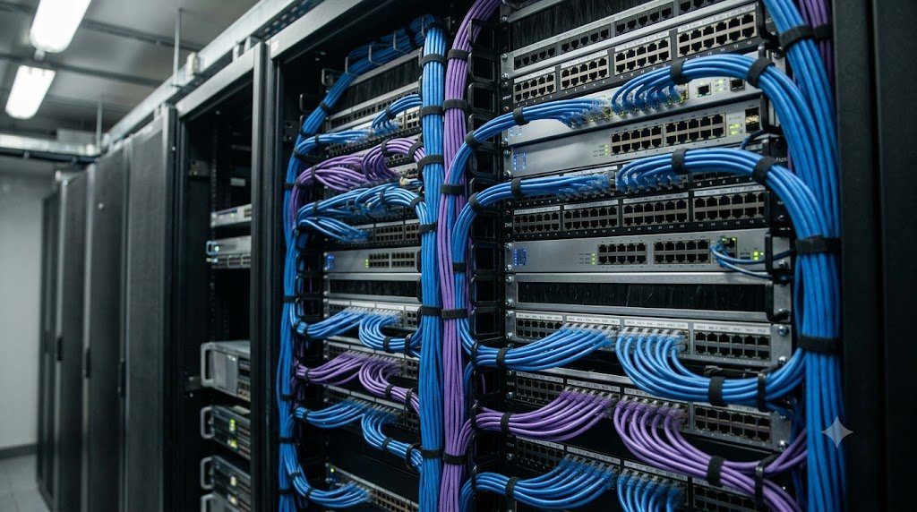
In the architectural evolution of modern enterprise and cloud computing data centers, traditional multi-tier hierarchical networking models—traditionally consisting of Access, Distribution, and Core switching layers—have encountered insurmountable physical limitations. Historical three-tier topologies were engineered primarily for North-South Traffic Patterns (client requests entering from the external WAN and traveling down to web servers). However, modern distributed cloud architectures, big-data clustering, and microservice virtualization generate overwhelming East-West Traffic Flows (server-to-server and compute-to-storage communication within the data center hall).
Structural Topography: Leaf Layer vs. Spine Layer Roles
The physical components of a modern two-tier Clos network perform distinct, highly specialized functions:
- Leaf Switches (Top-of-Rack / ToR): Physical access switches mounted directly inside server equipment racks. Leaf switches aggregate connections from physical compute servers, SAN storage arrays, and GPU clusters via 10G/25G/100G downlinks. Crucially, leaf switches never connect directly to other leaf switches; all leaf-to-leaf traffic must traverse the spine layer.
- Spine Switches: High-density, high-throughput core switching engines (utilizing 100G, 400G, or 800G optical ports). Spine switches act purely as a high-speed routing backplane. Spine switches never connect directly to other spine switches and never terminate end-user servers; their sole mission is interconnecting all leaf nodes.
| Architecture Parameter | Traditional 3-Tier Model | Modern 2-Tier Spine-and-Leaf Fabric |
|---|---|---|
| Traffic Optimization | North-South (Client to Server) | East-West (Server to Server Microservices) |
| Forwarding Mechanism | Layer 2 Spanning Tree (STP) | Layer 3 BGP / OSPF with Equal-Cost Multi-Path (ECMP) |
| Link Utilization | 50% (Spanning Tree blocks redundant links) | 100% Active-Active (All links forward simultaneously) |
| Hop Count & Latency | Variable (2 to 6 hops; unpredictable latency) | Deterministic Exactly 2 Hops (Sub-microsecond latency) |
| Horizontal Scalability | Complex vertical chassis upgrades (Scale-Up) | Seamless horizontal spine additions (Scale-Out) |
Layer 3 Routing and Equal-Cost Multi-Path (ECMP) Mechanics
The fatal flaw of traditional Layer 2 data center fabrics was their reliance on Spanning Tree Protocol (STP), which intentionally places half of all physical fiber links into a disabled ‘blocking’ state to prevent loops. In a spine-and-leaf fabric containing 16 spine switches, blocking 15 links would waste 94% of available backplane capacity.
Modern spine-and-leaf fabrics operate as fully routed Layer 3 Networks utilizing Interior BGP (eBGP per leaf) or OSPF/IS-IS. By running IP routing down to the top-of-rack leaf switches, the fabric leverages Equal-Cost Multi-Path (ECMP):
ECMP Bandwidth = Nspines × Interface Bandwidth (e.g., 16 × 100G = 1.6 Tbps Bisectional Bandwidth)
Forwarding ASICs execute CRC32 hashing across packet 5-tuples (Src/Dst IP, Protocol, Src/Dst Port), spraying independent conversation flows across all available spine switches simultaneously, delivering 100% active-active link utilization and instant microsecond failover if a single spine switch drops offline.
Oversubscription Ratio Calculations in Leaf Switches
Data center network designers must mathematically calculate the Oversubscription Ratio at the leaf tier to prevent buffer queuing drops during peak compute bursts:
Oversubscription Ratio = Total Downlink Capacity (to Servers) : Total Uplink Capacity (to Spines)
For example, if a leaf switch connects 48 servers at 25 Gbps ($48 \times 25\text{G} = 1,200\text{ Gbps}$ downlink) and connects to the spine layer via six 100 Gbps uplinks ($6 \times 100\text{G} = 600\text{ Gbps}$ uplink), the oversubscription ratio is $1200 : 600 = 2:1$. In high-performance AI training and distributed storage fabrics (NVMe-oF / RoCEv2), architects enforce a strict 1:1 non-blocking ratio, ensuring the network fabric can ingest full wire-rate throughput from every server simultaneously without dropping a single packet.
Network Virtualization: Overlay Networks via VXLAN EVPN
To allow virtual machines and containerized workloads to migrate freely across server racks without requiring complex Layer 2 physical VLAN extensions, modern spine-and-leaf fabrics deploy VXLAN (Virtual Extensible LAN) with BGP EVPN (Ethernet VPN, RFC 7432). The underlying IP spine-and-leaf fabric serves as the high-speed Underlay Network, while leaf switches act as Virtual Tunnel Endpoints (VTEPs) that encapsulate Layer 2 frames into Layer 3 UDP packets, creating an elastic, software-defined Overlay Network spanning the entire data center hall.
BGP as Data Center Fabric Routing Protocol (RFC 7938) and ASN Allocation Models
While interior gateway protocols like OSPF and IS-IS dominated historical enterprise data centers, modern hyperscale spine-and-leaf fabrics (such as those deployed by Meta, Google, and Amazon Web Services) universally deploy eBGP as the Underlay Routing Protocol, standardized under IETF RFC 7938 (‘Use of BGP for Routing in Large-Scale Data Centers’). eBGP was selected over link-state protocols due to its deterministic policy controls, superior failure domain containment, and predictable convergence behavior in massive Clos fabrics containing thousands of nodes.
In an RFC 7938 data center fabric, Autonomous System Numbers (ASNs) are allocated according to a strict hierarchical pattern utilizing private 2-byte or 4-byte ASNs (RFC 6996):
- Spine Layer ASN Architecture: All spine switches within a data center building share a single common ASN (e.g.,
AS 65100). Because spines never peer directly with each other, sharing an ASN prevents unneeded route advertisement between spines. - Leaf Layer ASN Architecture: Every individual Top-of-Rack (ToR) leaf switch is assigned its own unique, discrete ASN (e.g., Leaf-1 is
AS 65001, Leaf-2 isAS 65002, Leaf-N isAS 6500N).
Bisectional Bandwidth and Non-Blocking Fabric Scaling Mathematics
The definitive engineering metric of a Clos spine-and-leaf network is its Bisectional Bandwidth—the maximum throughput capacity achievable across the narrowest boundary dividing the network into two equal halves. In a symmetric Clos network with $L$ leaf switches, where each leaf has $k$ uplinks connecting to $S$ spines, the total aggregate bisectional fabric capacity is formulated as:
Bisectional Bandwidth = ½ · L · k · Blink [bps]
Where $B_{link}$ is the physical transceiver link speed (e.g., 100 Gbps, 400 Gbps). Because every leaf connects symmetrically to every spine, the fabric delivers uniform bisectional capacity: any server on Leaf A can communicate with any server on Leaf B at full line rate simultaneously, enabling massive parallel distributed computing for large language model (LLM) AI training clusters.
Hyperscale AI Cluster Teardown: RoCEv2 Congestion Spreads and PFC Deadlocks
In modern hyperscale AI supercomputing clusters running massive distributed Large Language Model (LLM) training jobs (such as training GPT-4 class models across 16,000 interconnected GPUs), standard TCP/IP networking introduces unacceptable CPU latency and memory copying overhead. AI data center architects deploy RDMA over Converged Ethernet (RoCEv2), which allows GPU memory on Server A to write directly into GPU memory on Server B over standard Ethernet spine-and-leaf fabrics with zero CPU involvement and sub-microsecond latency.
However, because RDMA protocol engines cannot tolerate a single dropped packet without initiating catastrophic pipeline retransmissions, RoCEv2 mandates a Lossless Ethernet Fabric enforced via Priority Flow Control (PFC / IEEE 802.1Qbb). During an intensive multi-week LLM training run at an AI cloud provider, the entire GPU cluster suddenly froze in a catastrophic condition known as a PFC Deadlock.
Explicit Congestion Notification (ECN) and Dynamic Deadlock Detection
AI network architects eliminated PFC deadlocks by implementing a multi-layered congestion management architecture: (1) Explicit Congestion Notification (ECN, RFC 3168) with Random Early Detection (RED): When switch buffers reach 60% capacity, the ASIC marks the ECN bits in packet IP headers. The receiving GPU detects the ECN mark and transmits a Congestion Notification Packet (CNP) back to the sender, throttling the sender’s transmission rate before buffers overflow, and (2) Hardware PFC Deadlock Watchdog Timers: If a queue remains paused for longer than 100 milliseconds, the switch ASIC automatically drops the paused packets to break the circular dependency loop, restoring cluster execution.
Data Center Fabric Telemetry: Streaming Telemetry (gNMI) and Buffer Monitoring
Managing a 400G spine-and-leaf Clos network cannot be accomplished using legacy SNMP polling. In a fabric processing billions of packets per second, polling switch counters once every 5 minutes (SNMP standard interval) fails to detect Microburst Congestion Events—traffic bursts lasting only a few milliseconds that fill on-chip packet buffers and trigger drops before SNMP can register a change.
Modern data center operating systems (such as Arista EOS, Cisco NX-OS, and SONiC) deploy Streaming Telemetry utilizing gNMI (gRPC Network Management Interface) and Protocol Buffers. Switch forwarding ASICs stream real-time queue depths, ingress/egress link counters, and dropped packet metadata continuously over high-speed HTTP/2 connections to centralized time-series databases (such as Prometheus or InfluxDB), providing microsecond-level visibility into fabric buffer health.
Optical Circuit Switching (OCS) and Hyperscale AI Network Topologies
As artificial intelligence supercomputing clusters scale to hundreds of thousands of interconnected GPUs, the electrical power consumed by electronic packet switching ASICs and optical transceivers becomes a dominant limiting factor. To break through this barrier, leading cloud research facilities (such as Google Jupiter) are pioneering Optical Circuit Switching (OCS).
An Optical Circuit Switch replaces electronic routing silicon with microscopic, motorized silicon micro-electromechanical (MEMS) mirrors operating inside an optical matrix. Instead of converting photons of light into electrical bits, processing them in silicon ASICs, and converting them back to light, the MEMS mirrors physically steer the laser light beams through free space directly between fiber ports. Optical circuit switching consumes near-zero electrical power, introduces zero packet latency, and operates completely independent of data rate—forwarding 100G, 800G, or 1.6T data streams with identical, flawless optical fidelity.
Integrated Infrastructure Engineering: Physical Plants, Data Center Fabrics and Software-Defined WAN
Beneath the abstract protocols, software routing daemons, and application data streams of modern telecommunications lies the physical reality of Network Infrastructure Engineering. High-performance enterprise networks, hyperscale cloud data centers, and global telecom central offices rely on the uncompromising convergence of Structured Cabling Plants, Non-Blocking Clos Topologies, Rack Thermal Fluid Dynamics, and Software-Defined Overlay Fabrics.
The operational framework of carrier-grade network infrastructure comprises four interdependent disciplines:
- Physical Plant Structured Cabling (ANSI/TIA-568): Engineering modular, standardized structured cabling subsystems across Entrance Facilities, Equipment Rooms, and Telecommunications Rooms. Managing 100-meter horizontal channel constraints, MPO/MTP multi-fiber trunk polarity (Methods A, B, C), and enforcing Tier 1 (OLTS) and Tier 2 (OTDR) field certification testing guarantees physical layer longevity across multiple active hardware lifecycles.
- Non-Blocking Data Center Clos Fabrics: Replacing legacy three-tier spanning-tree architectures with modern two-tier Spine-and-Leaf Clos networks. Leveraging Layer 3 eBGP routing (RFC 7938) and Equal-Cost Multi-Path (ECMP) delivers deterministic two-hop latency, non-blocking bisectional bandwidth, and 100% active-active link utilization optimized for intensive East-West cloud and AI cluster traffic.
- Thermodynamic Rack Thermal Management: Eliminating bypass air mixing through strict Hot Aisle / Cold Aisle containment (HAC/CAC) adhering to ASHRAE TC 9.9 guidelines. Maximizing CRAH heat exchange efficiency and deploying blanking panels slashes data center energy waste, driving Power Usage Effectiveness (PUE) down to world-class ratings beneath 1.15.
- Software-Defined WAN (SD-WAN) and SASE: Decoupling logical corporate WAN overlays from physical telecommunications underlays. Dynamic application-aware routing over encrypted IPsec tunnels provides automated circuit failover across commodity broadband and 5G, converged with cloud-native Secure Access Service Edge (SASE) security architectures to protect distributed global enterprises.
Data Center Infrastructure Management (DCIM) and Predictive Capacity Planning
Maintaining multi-megawatt mission-critical infrastructure requires 24/7/365 automated visibility through integrated Data Center Infrastructure Management (DCIM) suites. IoT sensor networks continuously sample rack intake temperatures, static pressure differentials, and electrical power branch circuit metrics. Predictive capacity planning algorithms forecast electrical draw and cooling headroom months in advance, ensuring that enterprise facilities expand compute density safely without thermal throttling or electrical circuit breaker tripping.