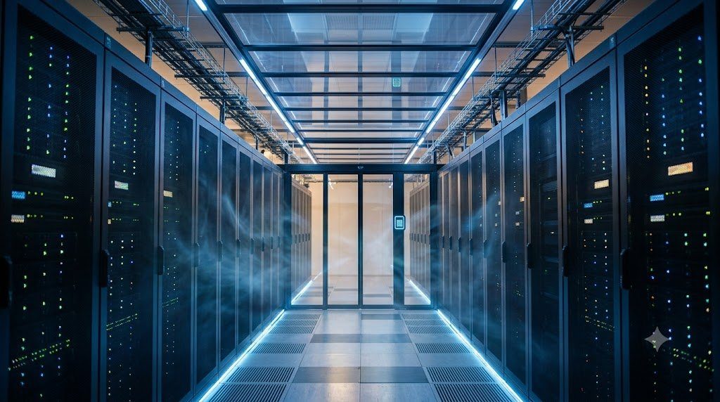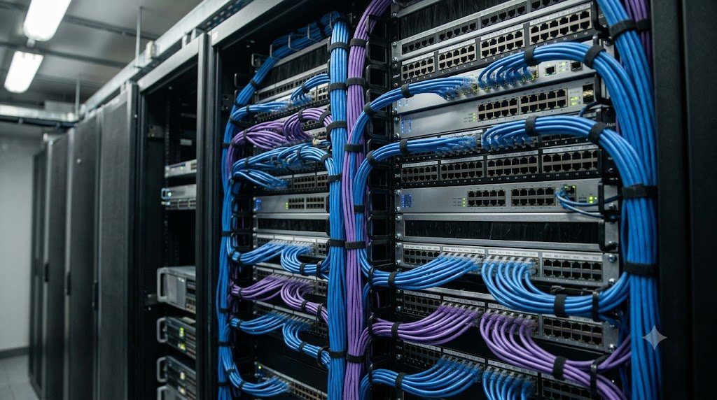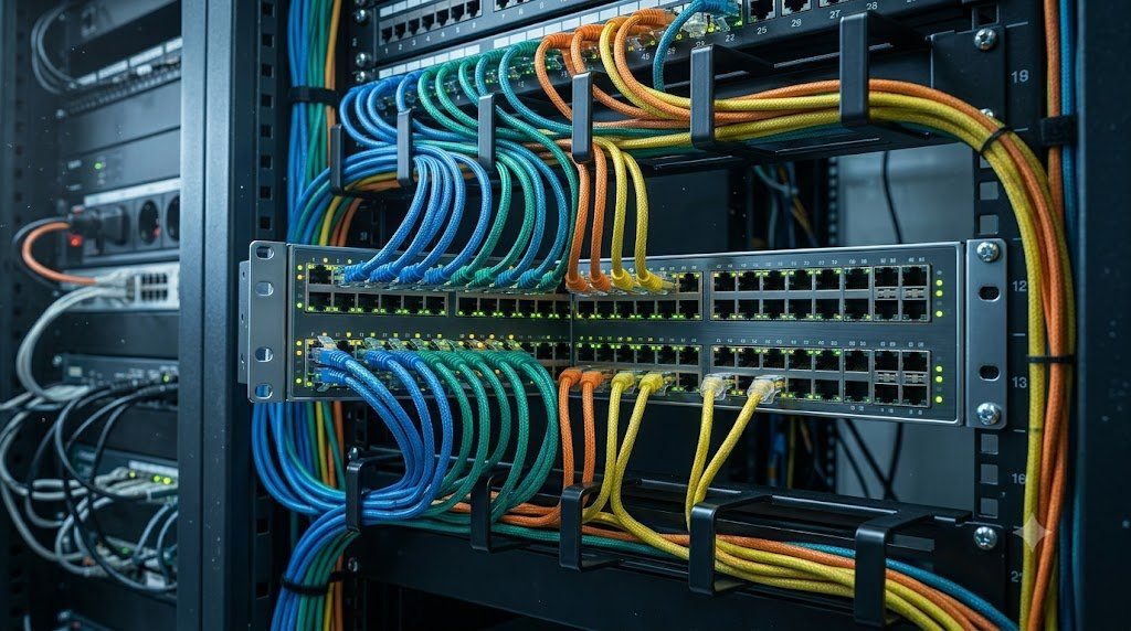
In local area network engineering, Layer 2 Ethernet Switching represents the hardware foundation of high-speed data communications. Standardized under IEEE 802.3 and IEEE 802.1D, modern Ethernet switches have completely replaced legacy collision-prone hubs. By micro-segmenting local networks into dedicated, full-duplex collision domains and forwarding frames based on 48-bit Media Access Control (MAC) addresses, switching matrices achieve wire-rate multi-gigabit throughput across enterprise campuses and cloud data centers.
The Dynamic MAC Address Learning Process and CAM Memory
When an Ethernet frame ingresses a switch port, the switch forwarding ASIC inspects the Source MAC Address within the Layer 2 frame header. It pairs the source MAC address with the ingress physical port identifier and active VLAN ID, recording the entry in its hardware Content-Addressable Memory (CAM) table:
| Destination MAC Address | VLAN Identifier | Associated Physical Port | Entry Type | Aging Timer (Seconds) |
|---|---|---|---|---|
| 00:1A:2B:3C:4D:01 | VLAN 10 (Engineering) | GigabitEthernet 1/0/1 | Dynamic (Learned) | 300 Seconds |
| 00:1A:2B:3C:4D:02 | VLAN 10 (Engineering) | GigabitEthernet 1/0/2 | Dynamic (Learned) | 284 Seconds |
| 00:1A:2B:3C:4D:88 | VLAN 20 (Finance) | GigabitEthernet 1/0/24 | Dynamic (Learned) | 300 Seconds |
| FF:FF:FF:FF:FF:FF | All VLANs | CPU / All Ports | Static (Broadcast) | Permanent (No Aging) |
Dynamic CAM entries maintain a standard aging timer (default 300 seconds). If a host remains silent and transmits no frames for five minutes, its CAM entry is purged. If a frame arrives destined for a MAC address not currently present in the CAM table (an Unknown Unicast), the switch must flood the frame to all ports within that VLAN to trigger a client response and re-learn the port location.
Virtual Local Area Networks (VLANs) and IEEE 802.1Q Encapsulation
Without logical segmentation, all devices plugged into a flat Layer 2 switch reside within a single flat Broadcast Domain. Broadcast frames (such as ARP requests and DHCP discovers) must be processed by the CPU of every connected device, wasting bandwidth and exposing networks to security eavesdropping. VLANs (IEEE 802.1Q) partition a single physical switch into multiple isolated logical broadcast domains.
To transport multiple VLANs across a single physical inter-switch link (a Trunk Link), Ethernet frames are modified by injecting a 4-byte IEEE 802.1Q Tag directly into the Ethernet header between the Source MAC address and EtherType fields:
- Tag Protocol Identifier (TPID – 16 bits): Set to
0x8100to identify the frame as 802.1Q tagged. - Priority Code Point (PCP – 3 bits): Encodes 802.1p Quality of Service (QoS) classes (0 to 7) for traffic prioritization.
- Drop Eligible Indicator (DEI – 1 bit): Indicates frames eligible to be dropped during buffer congestion.
- VLAN Identifier (VID – 12 bits): Specifies the VLAN number, supporting up to 4,094 unique VLANs (VID 0 and 4095 are reserved).
Broadcast Storms, Bridging Loops and Spanning Tree Mitigation
To guarantee network uptime, network architects install redundant physical cabling between switches. However, because Layer 2 Ethernet frame headers possess no Time-to-Live (TTL) counter (unlike Layer 3 IP packets), a physical loop causes broadcast frames to circulate endlessly in both directions, multiplying exponentially into a catastrophic Broadcast Storm that saturates link bandwidth and crashes switch CPUs within seconds.
To permit physical redundancy while mathematically eliminating Layer 2 loops, switches execute the Spanning Tree Protocol (IEEE 802.1D / 802.1w Rapid Spanning Tree / 802.1s Multiple Spanning Tree). Switches exchange Bridge Protocol Data Units (BPDUs), elect a central Root Bridge, calculate loop-free shortest paths, and dynamically place redundant backup links into an alternate ‘Blocking’ state, unblocking them in sub-second failover times if the primary path fails.
Modern Data Center Fabrics: VXLAN and EVPN Beyond Spanning Tree
In modern cloud data centers, Spanning Tree’s blocking of 50% of available link bandwidth is unacceptable. Modern data centers replace spanning tree with Virtual Extensible LAN (VXLAN, RFC 7348). VXLAN encapsulates Layer 2 Ethernet frames inside standard Layer 3 UDP packets (UDP port 4789), scaling VLAN limitations from 4,096 up to 16 million VNIs (VXLAN Network Identifiers) and enabling Equal-Cost Multi-Path (ECMP) routing across all spine-and-leaf links.
ASIC Memory Topologies: Shared Memory Architecture vs. Crossbar Ingress Buffering
In modern enterprise Ethernet switches (such as those powered by Broadcom Trident/Tomahawk or Cisco Silicon One architectures), the internal physical data plane must forward tens of millions of Ethernet frames per second with sub-microsecond latency. The engineering performance of a switch is fundamentally dictated by its internal Packet Buffer Memory Architecture, which absorbs microbursts when multiple high-speed ingress ports simultaneously transmit traffic toward a single congested egress port.
Switch buffer architectures are categorized into two primary models:
- Centralized Shared Memory Architecture: All switch ports share a high-bandwidth monolithic pool of on-chip SRAM buffer memory (typically 16 MB to 64 MB). When a frame arrives, the packet payload is written once into shared memory, and only a lightweight 64-byte descriptor pointer is queued in the egress port scheduler. This delivers the highest memory efficiency because unused buffer capacity is dynamically allocated to whichever port is experiencing traffic bursts.
- Combined Input-Output Queued (CIOQ) Architecture: High-density modular chassis switches utilize distributed input buffers and output buffers interconnected via a high-speed crossbar fabric. Operating at an internal fabric speedup factor ($S \ge 2$), CIOQ fabrics guarantee wire-rate line-card forwarding while eliminating output port contention through Virtual Output Queuing (VOQ).
CAM Table Overflow Attacks and Dynamic MAC Limiting Defense
Because hardware Content-Addressable Memory (CAM) tables have fixed finite storage capacities (typically 16,000 to 128,000 entries), local area networks are vulnerable to CAM Table Overflow (MAC Flooding) Attacks. An attacker executes automated software (such as macof) to flood the switch with tens of thousands of bogus, randomized source MAC addresses per second. Once the CAM table fills completely, the switch can no longer learn legitimate addresses. Under default bridging rules, the switch falls back to Fail-Open Flooding—broadcasting every subsequent unicast frame to every physical port on the switch, turning the secure switch into a legacy hub and allowing the attacker to sniff all network traffic. Switches defeat this via Port Security (MAC Limiting): restricting the maximum number of learned MACs per port (e.g., maximum 2) and automatically disabling the port upon violation.
Enterprise Banking Network Collapse: Spanning Tree BPDU Inversion and Root Bridge Stealing
In a catastrophic operational outage at a major commercial financial institution, the entire headquarters trading floor and retail banking core suffered a complete, simultaneous network blackout. Core switches, branch routers, and virtualization clusters experienced 100% CPU utilization, console ports became completely unresponsive, and network monitoring dashboards crashed under a relentless flood of billions of broadcast frames.
The root cause was traced to an unauthorized action by an entry-level technician in a remote wiring closet. The technician had connected a decommissioned, legacy 10/100 Mbps desktop switch to an open access wall jack to test an IP phone. Under IEEE 802.1D Spanning Tree rules, the switch with the Lowest Bridge Priority is elected as the central Root Bridge of the entire enterprise local area network (default priority 32768, with Bridge MAC address acting as tie-breaker).
Engineering Hardening Mandates: BPDU Guard and Root Guard
The disaster prompted immediate enterprise-wide deployment of Spanning Tree defense mechanisms: (1) BPDU Guard: Configured on 100% of user-facing edge ports (Cisco spanning-tree portfast bpduguard enable); if any BPDU is received on an access port, the switch instantly places the port into err-disabled state, neutralizing rogue switches in under 1 millisecond, and (2) Root Guard: Configured on distribution-to-access downlinks, preventing external ports from ever becoming root ports.
Advanced Layer 2 Hardening: Storm Control, Private VLANs and DAI Configuration
In enterprise multi-tenant switching environments and campus networks, securing Layer 2 broadcast domains against accidental loops, broadcast storms, and malicious network scanning requires proactive deployment of hardware-enforced port security features.
Network engineers configure standardized Layer 2 defense suites:
- Broadcast & Multicast Storm Control: Enforces hardware traffic policers on edge access ports (e.g.,
storm-control broadcast level 1.00). If broadcast traffic exceeds 1.0% of total interface bandwidth, the switch ASIC drops excess broadcast frames in silicon, preventing spanning-tree storms from impacting the wider network. - Private VLANs (PVLANs / RFC 5517): Subdivides a single VLAN broadcast domain into isolated secondary sub-domains: Promiscuous Ports (default gateways that communicate with all devices), Isolated Ports (client devices that can only talk to the promiscuous gateway and are completely blocked from communicating with each other), and Community Ports (devices that can communicate within their designated group). PVLANs are universally deployed in hotel Wi-Fi, university networks, and DMZ server farms to eradicate lateral malware movement.
interface GigabitEthernet1/0/10
 switchport mode access
 switchport access vlan 20
 switchport nonegotiate
 spanning-tree portfast
 spanning-tree bpduguard enable
 ip dhcp snooping limit rate 15
 ip verify source
 storm-control broadcast level 1.00
Time-Sensitive Networking (TSN / IEEE 802.1Q) and Deterministic Industrial Ethernet
Standard commercial Ethernet is inherently non-deterministic: packet queuing and CSMA/CD or buffer contention introduce variable queuing latency and packet jitter. While acceptable for web browsing and enterprise applications, non-deterministic latency is completely unacceptable for industrial motion control, automotive drive-by-wire steering, and professional live audio/video production.
To provide microsecond-level deterministic guarantees over standard Ethernet switching, the IEEE established the Time-Sensitive Networking (TSN) suite of amendments to IEEE 802.1Q:
- IEEE 802.1AS (Generalized Precision Time Protocol / gPTP): Synchronizes all clocks across the switching fabric to sub-microsecond precision.
- IEEE 802.1Qbv (Time-Aware Shaper): Implements a rotating scheduled transmission gate in switch output queues, guaranteeing that time-critical traffic traverses the switch matrix with zero buffer delay and zero jitter.
- IEEE 802.1Qbu (Frame Preemption): Allows high-priority industrial packets to interrupt and preempt an ongoing low-priority data frame midway through transmission, slashing latency spikes.
Integrated Ethernet Systems Engineering: Physical Transmission, Switching Matrices and Fabric Resiliency
Since its invention at Xerox PARC by Robert Metcalfe in 1973, Ethernet (IEEE 802.3) has evolved from a primitive 2.94 Mbps coaxial shared-medium broadcast bus into the universal, undisputed physical and data link layer foundation of global digital computing. Modern enterprise campuses and cloud data centers depend upon the seamless interoperability of Balanced Twisted-Pair Copper, High-Speed Optical Transceivers, Wire-Rate Layer 2 Switching ASICs, and Multi-Chassis Link Aggregation.
The engineering design philosophy governing modern Ethernet infrastructure encompasses four essential tenets:
- Transmission Line Integrity (Layer 1): Enforcing rigorous physical media standards: balanced differential signaling and alien crosstalk suppression in Category 6A/8 copper cabling, and total internal reflection waveguides in singlemode (OS2) and multimode (OM4) optical fibers. Designing link budgets with adequate optical power margins and enforcing IEC 61300-3-35 connector inspection standards guarantees zero physical layer bit errors.
- Deterministic Layer 2 Forwarding (Layer 2): Micro-segmenting local broadcast domains via IEEE 802.1Q VLAN trunking and Content-Addressable Memory (CAM) tables. Forwarding ASICs execute wire-rate MAC learning and filtering in silicon, preventing unknown unicast flooding and isolating departmental network domains.
- Loop Elimination and Active-Active Multi-Pathing: Replacing blocking Spanning Tree topologies with dynamic Link Aggregation Groups (LACP / IEEE 802.3ad), Multi-Chassis MLAG, and data center VXLAN EVPN overlays. This enables 100% active-active link utilization, sub-second deterministic failover, and non-blocking bisectional bandwidth across enterprise fabrics.
- Hardware Security Hardening: Implementing hardware-enforced port security suites: Storm Control, BPDU Guard, Root Guard, DHCP Snooping, Dynamic ARP Inspection (DAI), and MAC limiting to permanently neutralize broadcast storms, rogue switches, and Layer 2 man-in-the-middle attacks.
Energy Efficient Ethernet (EEE / IEEE 802.3az) and Green Enterprise Switching
In massive enterprise campus and data center installations housing tens of thousands of active switch ports, idle electrical consumption represents a major operational cost. Modern switches enforce Energy Efficient Ethernet (EEE / IEEE 802.3az). During periods of low traffic activity, the physical layer transceiver enters Low Power Idle (LPI) mode, powering down internal transmitter circuitry while maintaining link synchronization, reducing physical interface power consumption by up to 70% and contributing to enterprise corporate sustainability mandates.